Sunday, October 28, 2018

Ground Control - aerial photograph Ground Control

Ground Control - aerial photograph


Ground Control


Profile picture for user Haseeb Jamal
By: Haseeb Jamal SHALLOW

In order to produce an accurate map from aerial photograph it is absolutely necessary to established ground control. It consists in locating the positions of a no of pts. All over the area to be surveyed det their levels. These control pts short be such that can be easily identified on the photographs. Horizontal control is established by tiring or traversing. Vertical control is established through the use of ‘aneroid barometers’ or ‘Altimeters’

Applications of Air Photograph:

The practical uses of air photography are unlimited. Some of the application are listed below:
  • Town and country planning and developed estate man agent and economic planning are used both maps based on air survey and individual photography’s.
  • suitability of roads and rail alignments can be studied both for traffic flow an economy of construction.
  • Forestry and geology both use air maps and photography for the study of nature of areas and changes that take place.
  • Flood control planning can be based on air survey made at suitable intervals of time
  • Air survey provides means of mapping large undeveloped areas of the world.
  • For large scale engineering and redevelopment projects, reconnaissance can be undertake in to a large extend form air photograph.
  • Survey for accessing damage due to earth quake, crop dieses can be quickly estimated from air photograph.
  • Pollution effects form industrial wastes on land and water can be studied.

Tunnels:

Tunnels are constructed in order
  • To meet the req of rapid transportation in big cities.
  • To connect by shortest route, two termination separated by mountain.
  • To reduce very steep grades.
  • To avoid the excessive cost of mantaineice of an open cut subjected to land slides or snow drifts.
  • To avoid the expensive acquisition of valuable built up land, tearing up pavements and holding up traffic for long periods in large cities
  • When the depth of ordinary cutting exceeds 20m and the ground rises rapidly for a considerable distance after wards.

Chief considerations in location of a tunnel are

  • If should follow the best line adopted to the proposed traffic.
  • If should be most economical in construction an operation.
  • Convenience Ingress (enter) and Egress (leave)

Tunneling involves the following operatios:

  • Surface Survey
  • Transferring the alignment under ground
  • Transferring levels under ground

    SURFACE SURVERY:

This includes
  • A preliminary survey by transit and staid for 2-3miles (3-4km) on either side of the proposed alignment.
  • A plan (map) with a scale of say 1 in with contours drawn at 5m (20) intervals.
  • Final alignment is selected form this plan.
  • A detail survey of the geological information of strata as the cost of tunneling depends upon the nature of materials to be encountered.
The proposed route having been decided upon, the following pts require consideration.
  1. Alignment of the centre line of the tunnel.
  2. Gradient to be adopted.
  3. Determination of the exact length of tunnel.
  4. Establishment of permanent stations marking the line.
Control surveys for tunnel layouts are performed on ht surface joining the terminal pts of the tunnel is shown in figure (1).
Transferring the alignment under ground:

This is the most difficult and important operation in setting out a tunnel.
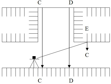
  • Fix two timber beams C and D as shown in figure two across the top of the shaft near its edges perpendicular to the direction of tunnel and as far apart as possible.
  • A threadlike is set up at a ground at a pre-determined station on a centre. Line mark one ground surface and another stations is again on the centre line itself.
  • The centre line is very carefully set up on the beams preferably on the plates fixed on a beam and drilled with hole for suspending wires by repetition observing and averaging the result.
  • From these pts two long penal wire with heavy plumb hobs 10 to 15 kg attacked to their lower edges or suspended down the shaft.
  • At the bottom these plumb bobs are immured in bucket of water, oil etc to eliminate oscillation.
  • Great care must be taken that wires and plumb bobs are hanging free. As a check the dist b/w the wires at the top and at the bottom of the shaft is to be measured and this should be the same.
  • The line joining the two wires gives the dir of alignment under ground.
  • The theodolite is transfer to the bottom of shaft and through the no of trails suspended wires.
  • Now the alignment is marked on marks driven into the whole i.e, E drilled on the roof.

Transferring levels under ground:

Leveling on the surface is done in the usual way and the levels are transfer underground at the ends of the tunnel from the nearest bench mark.
In case of transfer of levels underground at the shaft. The steps involve are
  • A fine steel wire loaded with weight of 5 to 15 kg is passed over a pulley (w) at the top of the shaft and is lowered into the shaft as shown in fig.3
  • Tow fine wire AA and BB horizontally stretched at the top and bottom of the shaft rasp.
  • The steel wired lowered into the shaft is so adjusted that it is in contact with both the wires AA and BB.
  • The pts of contact are marked on a still wire by a piece of chalk or by some other marker.
  • The wire is withdrawn form the shaft and is stretched on the ground.
  • The dist b/t the two marks on he wire is measured using the measuring tape and this gives the level of the bottom of the shaft.

LATTIUDE AND LONGITUDE:

O = Centre of earth
N = North Pole
S = South Pole
Nos = Polar axis or polar diameter about which earth rotates.
A = Any point on surface of earth
The position of a place on the earth surface is specified by latitude and longitude. The semi circle ‘NAS’ passing through A and terminates by the Poles N and S is called Meridian of the place.

LATITUDE:

Latitude of a place is the angular distance measured from the equator towards the nearer Pole along the meridian of the place or latitude of any pt ‘A’ is angle or arc AA’’. Latitude can also be defined as the angular distance that the place is north or south of equator.
The earth sphere being divided into two hemispheres by the equator, the upper one containing the North Pole is called the northern hemisphere. While the lower one having the South Pole is called southern hemisphere. The place is said to have a north latitude if it is in the northern hemisphere and south latitude if it is in the southern hemisphere.
The latitude angle is meared (90) at the earth center. North or south from the equatorial plane. Latitude north of equator is considered positive and that south of equator negative.

LONGITUDE:

Longitude of a place is the angular distance b/t the meridian of a place and the standard prime meridian
Or
Longitude of any place ‘A’ is angle ‘LA’ measured in the equatorial plane b/t the standard meridian and the meridian through A.
Or
The meridian NGS passing through Greenwich England has been adopted internationally as the standard meridian. This meridian divides the sphere into two hemispheres. The longitude is measured from “O” to 180 either towards east or west. The west longitude is considered as positive and the east as negative. Longitude angles are measured at the earth centre east or west from the plane of ‘O’ longitude which has been arbitrary placed through green witch England.
Hence the position of place ‘A’ is completely specified by the latitude and longitude. These two terms give unique location of any pt on the earth. This system of geographic co-ordinates is used in navigation and Geodesy.

How to do Triangulation Survey


How to do Triangulation Survey


Profile picture for user Haseeb Jamal
By: Haseeb Jamal /HOW TO, NOTES

Triangulation work is carried out in following step.
  1. Reconnaissance
  2. Erection of Signals & Towers
  3. Measurement of Horizontal Angles
  4. Astronomical Observations Necessary to Determine the True Meridian and the Absolute Positions of the Stations
  5. Measurement of Baseline
  6. Adjustment of observed Angles
  7. Computations of Lengths of each side of each Delta Dash S
  8. Computations of the Latitude and Longitude of ST

1. Reconnaissance:

In geodetic Surveying, reconnaissance consists of: (See also: Reconnaissance in Transportation & Highway Engineering )
  1. Examination of the country to be surveyed.
  2. Selection of most favorable sides for base lines
  3. Selection of suitable positions of Delta Dash S station
  4. Determination of indivisibility of station

2. Selection of Station:

The selection of station is based upon the following consideration.
  1. The stations should be clearly visible from each other. For this purpose highest commanding positions such as top of hills or mountains is selected.
  2. They should form well shaped triangles
  3. They should be easily accessible
  4. They should be useful for detail survey
  5. Thy should be so fixed that the length of sight is not too short or too long

3. Inter-visibility and Heights of Stations:

For indivisibility of two stations they should be fixed on highest available ground. Such as mountain peaks rides or top of hills when the distance b/t the two stations is great and the difference in elevation b/t them is small then it is necessary to raise both the instrument and signal to overcome the curvature of the earth and to clear all the intervening obstruction.
The height of both the instrument and signal above the ground depends upon.
  1. Distance between the stations.
  2. Relative elevations of stations.
  3. The profile of intervening ground.

3. 1. Distance between stations:

If the intervening ground is free any obstruction, the distance of a visible horizon form a station of known elves above datum as well as the elves of the signal while may be just visible at a given distance can be determine from the formula. Station Distance Formula
Where
H = ht. of station above a datum
D = Dist from the station to point of tangent
R = mean radius of earth
M = co-efficient of refraction (0.07 for sight over land and 0.08 for sights over water)
D1 and R being expressed in same units. Alternatively, if ‘h’ is in meter and D1 is in kilometer then
H (m) = 0.0673 D12 (km) ==> (A)
Or
H (ft) = 0.574 D1 (miles) ==> (B)
D1 and D2 can be determined and dist b/t two stations will be (D1+ D2)

3. 2. Relative elevations of stations:

A and B are the two stations
D = dist b/t A and B in km
Ha = known elev of ‘A’ above a datum
H = required elev of ‘B’ above a datum
D1 = distance (km) of ‘A’ from pt of tangency (p)
D2 = distance (km) of ‘B’
Dist D1 can be calculated. Hence the required elev, h = 0.0673 D2
Ha = 0.0673 D12 or h = 0.0574 D22 (miles)
D1 Or D1 Miles
Now D2 = D - D1
Height or signal / Tower/ scaffold a B = Elev of datum + h - R.L of st B elev of line sight
NOTE:
The line of sight should not be near the surface of ground at pt of tangency on account of strata of disturbed air and should be kept at least 2m (61) above the ground preferably 3m (1D) and this allowance (clearance) should be made in deterring the heights of stations.

3. 3. Profile of intervening ground:

If the peaks in the intervening ground are likely to obstruct, the line of sight, their elevations and locations must be determined.

Procedure:

The elevation of line of sights at the respective points can be computed and the results compared with the ground elevation at those points to determine weather the line of sight clears all the intervening obstruction.

What is Phototheodolite and Applications of a Photo theodolite

What is Phototheodolite and Applications of a Photo theodolite

By: Haseeb Jamal NOTES, SURVEYING EQUIPMENT
Phototheodolite
 
 
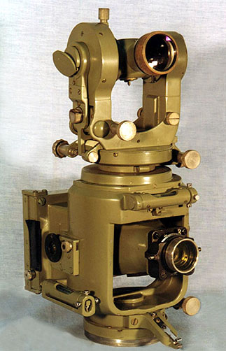
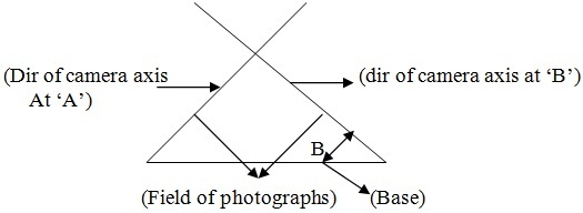
A photo theodolite is a form of ground camera. It is a combination of camera and theodolite and is used for taking photographs and measuring the angles which the rival plane of collimation makes with base line. Both the theodolite and the camera rotate about a common vertical axis. The instrument is used for terrestrial photogrammetry
It should be noted that the pointing of the theodolite is completely independent of that of the camera, but the horizontal circle, which is located on the top of the camera housing, is fixed in such a way that when the circle reading is zero, the optical axes of the theodolite and camera lie in the same vertical plane. This means that all horizontal directions observed with the theodolite can be easily related to the principal point of the photograph.

Applications of Phototheodolite

Not only is the terrestrial camera useful for mapping construction sites at scales as large as 5 ft. to 1 in., but the photographs can be utilised in a suitable instrument for taking off quantities for earthworks or stock-piles and for directly plotting tunnel profiles and other varied uses. At the other extreme the photo-theodolite can be employed for mapping at small scales and even for extending control.

The Future Role of Geoinformation


The Future Role of
Geoinformation
I recently attended a seminar on the application of 3D, virtual reality (VR) and augmented reality (AR) for local authorities in The Netherlands. A couple of years ago, VR and AR were announced to much fanfare as the next big thing that would revolutionise the surveying profession. But not much has actually happened since then. Well, maybe I am exaggerating a little, but the proclaimed transformation to an immersive or interactive environment has not taken place on such a scale as to send massive shock waves through the geospatial industry. However, the event I attended highlighted a surprisingly large number of applications for implementing these technologies – and not just for the sake of being a front runner and
demonstrating how slickly your organisation has entered the modern era.

Instead, 3D and VR/AR techniques are being used to inform citizens about the impact of the installation of new wind turbines, for example. 3D modelling is already widely used by geomatics professionals, of course. However, it is now increasingly becoming a tool used by local governments too. Obviously, 3D models are very suitable for visualising development plans,
and they help to involve citizens in the planning process. How will the direct vicinity – their local neighbourhood – look after it has undergone major restructuring? 3D models, AR and VR offer tremendous possibilities for smoothing this process in completely new and innovative ways. Participatory spatial planning has only just begun! And with smart cities as one of the
key topics in the geospatial debate, it seems like everything is falling into place at the right time.
VR and AR are important elements to support the implementation of the smart city concept. All of this requires huge volumes of data, so superfast mobile internet is absolutely crucial. 5G will bring the solution, as it will interconnect and control machines, objects and devices in a fast and smart way. Combining 5G with 3D, VR and AR will catapult the smart city concept
so that these technologies will finally deliver on their promises. And as for geomatics, a smart city won’t be smart without it!
https://www.gim-international.com/content/blog/the-future-role-of-geoinformation

Thursday, October 18, 2018

What is Phototheodolite and Applications of a Photo theodolite

What is Phototheodolite and Applications of a Photo theodolite

By: Haseeb Jamal NOTES, SURVEYING EQUIPMENT
Phototheodolite
 
 
A photo theodolite is a form of ground camera. It is a combination of camera and theodolite and is used for taking photographs and measuring the angles which the rival plane of collimation makes with base line. Both the theodolite and the camera rotate about a common vertical axis. The instrument is used for terrestrial photogrammetry
It should be noted that the pointing of the theodolite is completely independent of that of the camera, but the horizontal circle, which is located on the top of the camera housing, is fixed in such a way that when the circle reading is zero, the optical axes of the theodolite and camera lie in the same vertical plane. This means that all horizontal directions observed with the theodolite can be easily related to the principal point of the photograph.

Applications of Phototheodolite

Not only is the terrestrial camera useful for mapping construction sites at scales as large as 5 ft. to 1 in., but the photographs can be utilised in a suitable instrument for taking off quantities for earthworks or stock-piles and for directly plotting tunnel profiles and other varied uses. At the other extreme the photo-theodolite can be employed for mapping at small scales and even for extending control.

How to do Trigonometric Surveying

How to do Trigonometric Surveying

NOTES, HOW TO, DEFINITION


Definition:

Geodetic or trigonometrically surveying takes into account the curvature of earth Since very extensive areas and very large distances are involved. In geodetic surveying highly refined instruments and methods are used. Geodetic work is undertaken by the state agency e.g. survey of Pakistan undertaken by the state agency.
  1. Triangulation
  2. Precise leveling

Object:

The object of geodetic surveying is to accurately determine the relative position of a sys of widely separated pts (stations) on the surface of earth and also their absolute positions.
Relative positions are determined in terms of azimuths and length f lines joining them. Absolute positions are determined in terms of latitude and longitudes and elevations above mean sea laves. The methods employed in geodetic surveying are:
  1. Triangulation (most accurate but expensive)
  2. Precise traverse (inferior and used when triangulation is physically impossible or very expensive) e.g. Densely wooded country.

Triangulation:

It is based on the trigonometry proposition that of one side and three angles be computed by the application of since rule. In this method suitable points called triangulation stations are selected and established throughout the area to be surveyed.
The stations may be connected by a series of triangles or a chain of quadrilaterals as shown.
Triangulation

Baseline:

Whose length is measured these stations form the vertices of a series mutually connected, triangles the complete figure being called ‘Triangulation system’. In this system of triangles one line say ‘AB’ and all the angles are measured with greatest care and lengths of all the remaining line in the system are then computed. For checking both the fieldwork and computation another line say GH is very accurately measured at the end of the system. The line whose length is actually measured is known as baseline or base and that measured for checking purpose is known as the check base.

Triangulation Figures:

The geometric figures used in triangulation system are (i) Triangles (ii) Quadrilaterals (ii) Quadrilaterals, Pentagon, hexagons with centre angle. This arrangement although simple and economical but less accurate since the number of conditions involve in its adjustment is small.
  1. Station adjustment ==> sum of angle is 180
  2. Figure adjustment ==> sum of angles is 400 grad or 360
  3. Quadrilateral; adjust ==> (all the angles are horizontal)
Equilateral triangulationQuadrilaterals pentagons or hexagonal with central stations. For very accurate work a chain of quadrilaterals may be used. There is no station at the intersection of diagonals. This system is most accurate since the number of conditions in its adjustments is much greater. To minimize the effect of small errors in measurement of angles the triangles hold be well shaped or well proportioned i.e. they should not have angle less than 30 or greater than 120.The best shape triangle is equilaterals triangle and best shape quadrilateral is square.
 

Subscribe to our Newsletter

Stay informed - subscribe to our newsletter.

How to do Triangulation Survey

How to do Triangulation Survey

Profile picture for user Haseeb Jamal
By: Haseeb Jamal /HOW TO, NOTES
 
 
Triangulation work is carried out in following step.
  1. Reconnaissance
  2. Erection of Signals & Towers
  3. Measurement of Horizontal Angles
  4. Astronomical Observations Necessary to Determine the True Meridian and the Absolute Positions of the Stations
  5. Measurement of Baseline
  6. Adjustment of observed Angles
  7. Computations of Lengths of each side of each Delta Dash S
  8. Computations of the Latitude and Longitude of ST

1. Reconnaissance:

In geodetic Surveying, reconnaissance consists of: (See also: Reconnaissance in Transportation & Highway Engineering )
  1. Examination of the country to be surveyed.
  2. Selection of most favorable sides for base lines
  3. Selection of suitable positions of Delta Dash S station
  4. Determination of indivisibility of station

2. Selection of Station:

The selection of station is based upon the following consideration.
  1. The stations should be clearly visible from each other. For this purpose highest commanding positions such as top of hills or mountains is selected.
  2. They should form well shaped triangles
  3. They should be easily accessible
  4. They should be useful for detail survey
  5. Thy should be so fixed that the length of sight is not too short or too long

3. Inter-visibility and Heights of Stations:

For indivisibility of two stations they should be fixed on highest available ground. Such as mountain peaks rides or top of hills when the distance b/t the two stations is great and the difference in elevation b/t them is small then it is necessary to raise both the instrument and signal to overcome the curvature of the earth and to clear all the intervening obstruction.
The height of both the instrument and signal above the ground depends upon.
  1. Distance between the stations.
  2. Relative elevations of stations.
  3. The profile of intervening ground.

3. 1. Distance between stations:

If the intervening ground is free any obstruction, the distance of a visible horizon form a station of known elves above datum as well as the elves of the signal while may be just visible at a given distance can be determine from the formula. Station Distance Formula
Where
H = ht. of station above a datum
D = Dist from the station to point of tangent
R = mean radius of earth
M = co-efficient of refraction (0.07 for sight over land and 0.08 for sights over water)
D1 and R being expressed in same units. Alternatively, if ‘h’ is in meter and D1 is in kilometer then
H (m) = 0.0673 D12 (km) ==> (A)
Or
H (ft) = 0.574 D1 (miles) ==> (B)
D1 and D2 can be determined and dist b/t two stations will be (D1+ D2)

3. 2. Relative elevations of stations:

A and B are the two stations
D = dist b/t A and B in km
Ha = known elev of ‘A’ above a datum
H = required elev of ‘B’ above a datum
D1 = distance (km) of ‘A’ from pt of tangency (p)
D2 = distance (km) of ‘B’
Dist D1 can be calculated. Hence the required elev, h = 0.0673 D2
Ha = 0.0673 D12 or h = 0.0574 D22 (miles)
D1 Or D1 Miles
Now D2 = D - D1
Height or signal / Tower/ scaffold a B = Elev of datum + h - R.L of st B elev of line sight
NOTE:
The line of sight should not be near the surface of ground at pt of tangency on account of strata of disturbed air and should be kept at least 2m (61) above the ground preferably 3m (1D) and this allowance (clearance) should be made in deterring the heights of stations.

3. 3. Profile of intervening ground:

If the peaks in the intervening ground are likely to obstruct, the line of sight, their elevations and locations must be determined.

Procedure:

The elevation of line of sights at the respective points can be computed and the results compared with the ground elevation at those points to determine weather the line of sight clears all the intervening obstruction.