Thursday, December 16, 2021

What are Survey Stations and How to Select a Survey Station


Definition

Survey Stations is a point of importance at the beginning and end of chain line. There are two types of survey stations:
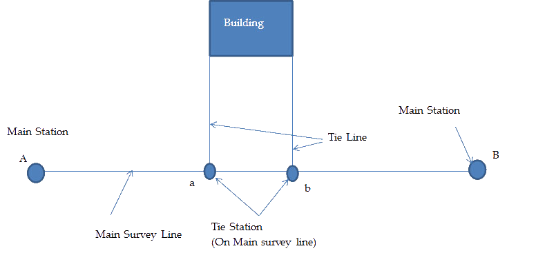
Main Station

  • These are the end of survey line i.e. which connects boundaries.
  • Line joining Main Stations is called Main Survey Line or Chain Line.
  • They are represented by Circle, Capital letters A B... Or number 1 2... Or (A)

Subsidiary or Tie Station

  • These are the points selected on main line, where it is necessary to run auxiliary lines to locate interior details such as corner, tree, building etc.
  • Lines joining tie station are called Tie Lines or Subsidiary Lines
  • They are represented by Small letters a, b,
Surveying Stations

Selection of Survey Station

The following points should be kept in mind while selecting a station:

  • The stations should be mutually inter-visible
  • Main principle of chain survey should strictly be observed
  • If possible, line through the whole length of area should be drawn
  • All triangles should be well defined
  • A check line should be provided in each triangle
  • Survey lines should be as few as possible
  • A number of tie lines should be drawn
  • Position of survey lines should be such that to avoid obstacles to chaining and ranging
  • It should be on level ground
  • The sides of triangle should pass as close to the boundary as possible.

Important Lines

  1. Base line
  2. Check line
  3. Tie line

Also See: Types of Surveying Chains

Base Line

  • The longest of the chain lines used in making a survey is generally regarded as Base line.
  • It is the most important line because it fixes up the direction of all other lines, since on base line, is built framework of a survey.
  • It should be laid on level ground, as possible through the center and length of the area.
  • It should be correctly measured and should be measured twice or thrice.

Check Line

  • A check line also called proof line is a line joining the apex of a triangle to some fixed point on the opposite side.
  • A check line is measured to check the accuracy of the framework.
  • Thus there is a complete check on the field measurement as well as on the accuracy of the plotting work.

Tie Line

  • A tie line is a line joining fixed points termed as Tie station on the main survey lines.
  • A tie line usually fulfill a dual purpose i.e. it checks the accuracy of the framework and enables the surveyor to locate the interior details which are far away from the main chain line
 
Let us know in the comments what you think about the concepts in this article!

Sunday, December 12, 2021

What is Electronic Distance Measurement ( EDM )?


What is Electronic Distance Measurement ( EDM )?


The main instrument for surveyors on site today is the ‘total station’ which is an example of electronic distance measurement. It is an instrument that combines the angle measurements that could be obtained with a traditional theodolite with electronic distance measurements. Taping distance, with all its associated problems, has been rendered obsolete for all baseline measurement. Distance can now be measured easily, quickly and with great accuracy, regardless of terrain conditions

Total stations with their inbuilt EDM enable:
(1) Traversing over great distances, with much greater control of swing errors.
(2) The inclusion of many more measured distances into control networks, rendering classical triangulation obsolete. This results in much greater control of scale error.
(3) Setting-out and photogrammetric control, over large areas, by polar coordinates from a single base line.
(4) Deformation monitoring to sub-millimetre accuracies using high-precision EDM, such as the Mekometer ME5000. This instrument has a range of 8 km and an accuracy of ±0.2 mm ±0.2 mm/km of the distance measured ignoring unmodelled refraction effects

Classification of electronic measurement instruments instruments

Historically EDM instruments have been classified according to the type and wavelength of the electromagnetic energy generated or according to their operational range. Very often one is a function of the other. For survey work most instruments use infra-red radiation (IR). IR has wavelengths of 0.8–0.9 µm transmitted by gallium arsenide (GaAs) luminescent diodes, at a high, constant frequency.
The accuracies required in distance measurement are such that the measuring wave cannot be used directly due to its poor propagation characteristics. The measuring wave is therefore superimposed on the high-frequency waves generated, called carrier waves. The superimposition is achieved by amplitude (Figure 4.14), frequency (Figure 4.15) or impulse modulation (Figure 4.16). In the case of IR instruments, amplitude modulation is used. Thus the carrier wave develops the necessary measuring characteristics whilst maintaining the high-frequency propagation characteristics that can be measured with the requisite accuracy.
In addition to IR, visible light, with extremely small wavelengths, can also be used as a carrier. Many of the instruments using visual light waves have a greater range and a much greater accuracy than that required for more general surveying work. Typical of such instruments are the Kern Mekometer ME5000, accurate to ±0.2 mm ±0.2 mm/km, with a range of 8 km, and the Com-Rad Geomensor CR204.